Roof Vibrations Column Beam Bending Problem

Bending Moment Diagram Fixed End Beam In 2020 Bending Moment Shear Force In This Moment

Combined Bending Axial Forces Beam Columns Ppt Video Online Download

Calculation Of Beam Deflection Architectural Engineering Structural Engineering Civil Engineering Construction

Draw The Shear Force And Bending Moment Diagrams For A Cantilever Beam In 2020 Bending Moment Shear Force In This Moment

Structural Steel Beam Loading Tables In 2020 Steel Beams Steel Beam Sizes Beams
Http Faculty Arch Tamu Edu Media Cms Page Media 4210 Ns13 2wooddesign 1 Pdf
This results in vibration modes involving several beams moving simultaneously together with an area of floor slab.
Roof vibrations column beam bending problem.

Portal Frame An Overview Sciencedirect Topics

Structural Beam Bending Stress Calculator Simply Supported On Both Ends Under Superimposed Loading Equations Engineers Edge Beams Equations I Beam
Http Files Engineering Com Download Aspx Folder 04bf3e85 Ec09 4674 B23a 62720c758f0e File Tips For Avoiding Crane Runway Problems Pdf

Bar Bending Schedule For Foundations Columns Beams And Slabs Engineering Basic Beams Column Structural Drawing

Chap 6 Compression Members Columns Beam Columns Columns Theory Bending Moment Concentric Eccentric Column

Pin On 3d Modeling Design

Influence Lines For Trusses Structural Analysis Review Structural Analysis Civil Engineering Design Structural Engineering

Crane Runway Beam Design Excel In 2020 Beams Design Concrete Design

Simply Supported Beam With Both Side Ovehang Help For Transtutors Civil Engineering Design Engineering Civil Engineering Construction

Structural Slab Formwork Components Slab Concrete Structure Sheathing
Http Www Cv Titech Ac Jp Courses Atce2 Lesson1 Pdf
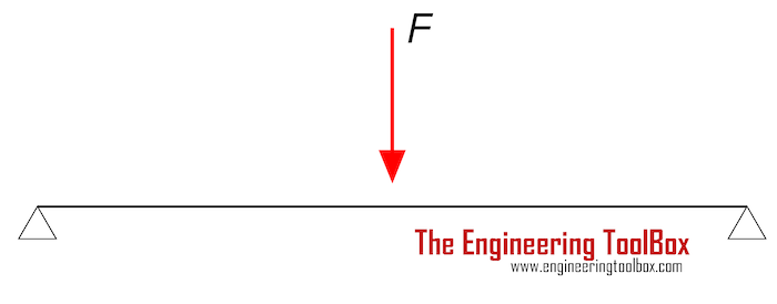
Beams Natural Vibration Frequency

Pin On Structural Engineering

Tips To Work Out The Total Loads On A Column And Related Footing Staircase Design Plan Design Design

Beam Column An Overview Sciencedirect Topics

Beam Stiffness An Overview Sciencedirect Topics
Http Www Seas Ucla Edu Wallace Files 20 20teaching 20page Ce 20142 Hand1 20w02 Pdf

Why Do We Provide Bent Up Bars In Slabs Quora
Https Encrypted Tbn0 Gstatic Com Images Q Tbn 3aand9gctbc Ibwjot2q6ww8ey62ftse8wgc4du0fcndph Tohk6qoxpn Usqp Cau

Seismic Performance Evaluation Of Damage Controlled Composite Steel Frame With Flexible Gel Covered Studs Sciencedirect

How Can You Differentiate Between In Plane And Out Plane Bending Moments

Pdf The Safety Of Common Steel Beam Column Connections In Fire
Https Www Tandfonline Com Doi Pdf 10 1080 13632469 2016 1233916

Allowable Bending Stress An Overview Sciencedirect Topics
Source : pinterest.com
